Product Description
| Item No. | φD | L | L1 | L2 | L3 | S | M | Tighten the strength(N.m) |
| SG7-10-14- | 15 | 20 | 6 | 6 | 3 | 1 | M3 | 1 |
| SG7-10-25- | 26 | 26 | 8 | 8 | 4 | 1 | M4 | 1.5 |
| SG7-10-30- | 32 | 32 | 10 | 9 | 5 | 1.5 | M4 | 1.7 |
| SG7-10-40- | 40 | 50 | 17 | 12 | 8.5 | 2 | M5 | 4 |
| SG7-10-55- | 56 | 58 | 20 | 14 | 10 | 2 | M5 | 4 |
| SG7-10-65- | 66 | 62 | 21 | 15 | 10.5 | 2.5 | M8 | 15 |
| SG7-10-80- | 82 | 86 | 31 | 18 | 15.5 | 3 | M8 | 15 |
| SG7-10-95- | 98 | 94 | 34 | 20 | 17 | 3 | M8 | 15 |
| SG7-10-108- | 108 | 123 | 46 | 24 | 23 | 3.5 | M8 | 15 |
1111
| Item No. | Rated torque | Maximum Torque | Max Speed | Inertia Moment | N.m rad | RRO | Tilting Tolerance | End-play | Weight:(g) |
| SG7-10-14- | 1.1N.m | 2.2N.m | 19000prm | 3.9×10⁻⁴kg.m² | 45N.m/rad | 0.02mm | 1.0c | +0.6mm | 20 |
| SG7-10-25- | 6.0N.m | 12N.m | 16000prm | 6.8×10kg.m² | 56N.m/rad | 0.02mm | 1.0c | +0.6mm | 25 |
| SG7-10-30- | 6.5N.m | 13N.m | 15000prm | 8.3×10kg.m² | 70N.m/rad | 0.02mm | 1.0c | +0.6mm | 46 |
| SG7-10-40- | 32N.m | 64N.m | 13000prm | 9.3×10kg.m² | 490N.m/rad | 0.02mm | 1.0c | +0.8mm | 135 |
| SG7-10-55- | 46N.m | 92N.m | 10500prm | 3.8×10⁻³kg.m² | 1470N.m/rad | 0.02mm | 1.0c | +0.8mm | 300 |
| SG7-10-65- | 109N.m | 218N.m | 8300prm | 8×10kg.m² | 2700N.m/rad | 0.02mm | 1.0c | +0.8mm | 570 |
| SG7-10-80- | 135N.m | 270N.m | 7000prm | 1.5×10⁻²kg.m² | 3100N.m/rad | 0.02mm | 1.0c | +1.0mm | 910 |
| SG7-10-95- | 260N.m | 520N.m | 6000prm | 1.9×10kg.m² | 4400N.m/rad | 0.02mm | 1.0c | +1.0mm | 1530 |
| SG7-10-108- | 430N.m | 860N.m | 5000prm | 3×10kg.m² | 5700N.m/rad | 0.02mm | 1.0c | +1.0mm | 2200 |
/* January 22, 2571 19:08:37 */!function(){function s(e,r){var a,o={};try{e&&e.split(“,”).forEach(function(e,t){e&&(a=e.match(/(.*?):(.*)$/))&&1
Durometer Hardness in Rubber Coupling Materials
Durometer hardness is a measure of the material’s resistance to indentation or penetration by a specified indenter. In rubber couplings, durometer hardness is a critical characteristic that influences their performance. It is typically measured using a durometer instrument.
The durometer hardness scale commonly used for rubber materials is the Shore durometer scale, indicated by a letter followed by a numerical value (e.g., Shore A, Shore D). Lower durometer values indicate softer and more flexible rubber, while higher values indicate harder and less flexible rubber.
In relation to rubber couplings:
- Higher Durometer (Harder Rubber): Couplings made from harder rubber materials have better torque transmission capabilities and higher load-bearing capacity. However, they may offer less vibration isolation and misalignment compensation.
- Lower Durometer (Softer Rubber): Couplings made from softer rubber materials provide greater flexibility, vibration damping, and misalignment compensation. They are suitable for applications where vibration reduction is crucial.
The choice of durometer hardness depends on the specific requirements of the application, including torque levels, vibration, misalignment, and desired performance characteristics.
Comparison of Rubber Couplings with Other Flexible Coupling Types
Rubber couplings, elastomeric couplings, and disc couplings are all flexible coupling options used in various mechanical systems. Here’s a comparison of rubber couplings with these alternatives:
Rubber Couplings:
- Transmit torque while damping vibrations through the flexibility of rubber elements.
- Provide good misalignment compensation and shock absorption.
- Relatively simple construction and cost-effective.
- Effective in reducing noise and vibration in applications.
- Suitable for moderate to high torque applications with moderate misalignment.
Elastomeric Couplings:
- Similar to rubber couplings, utilize elastomeric materials for flexibility and vibration damping.
- Offer higher torque capacity and stiffness compared to rubber couplings.
- Provide better misalignment compensation and torsional stiffness.
- Wider range of sizes and configurations for various applications.
- Commonly used in pumps, compressors, and other machinery.
Disc Couplings:
- Use a series of metal discs to transmit torque and accommodate misalignment.
- Offer high torsional stiffness and accuracy in torque transmission.
- Can handle higher speeds and torque compared to rubber or elastomeric couplings.
- Require precision in manufacturing and installation.
- Used in applications requiring high precision and minimal backlash.
When choosing between these flexible coupling types, considerations such as torque requirements, misalignment compensation, torsional stiffness, and application-specific needs play a significant role in making the appropriate selection. Each type has its advantages and limitations, making it important to assess the specific requirements of the machinery system.
Types of Rubber Couplings Designed for Specific Uses
There are several types of rubber couplings, each designed with specific characteristics to suit various applications:
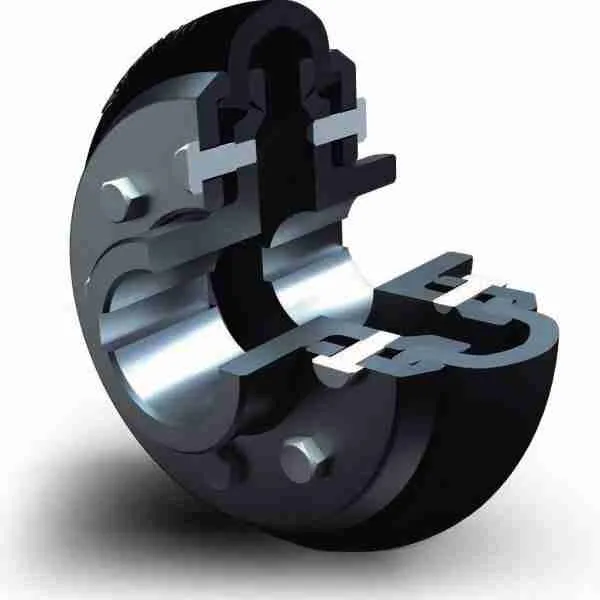
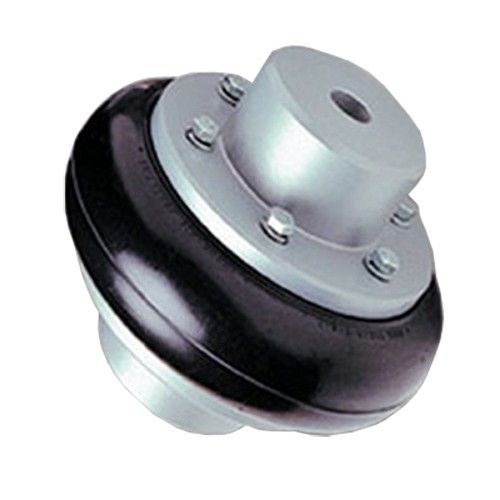
- Flexible Jaw Couplings: These couplings consist of two hubs connected by a flexible rubber element. They are commonly used in applications where misalignment, vibrations, and shocks need to be dampened, such as in pumps, fans, and compressors.
- Oldham Couplings: Oldham couplings use a rubber disk as the intermediate element between two hubs. They provide compensation for misalignment while maintaining a constant velocity between input and output shafts, often used in printing, packaging, and CNC machinery.
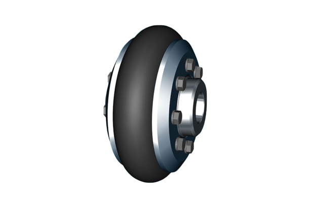
- Tyre Couplings: These couplings have a high degree of torsional flexibility and are suitable for applications with substantial misalignment and shock absorption requirements, like in heavy-duty machinery and construction equipment.
- Pin and Bush Couplings: These couplings use rubber bushes to provide vibration isolation and accommodate misalignment. They are used in various industrial applications, including conveyors, mixers, and crushers.
- Diaphragm Couplings: Diaphragm couplings use a flexible rubber diaphragm to transmit torque and compensate for misalignment. They are commonly found in precision equipment like servo motors and robotics.
Each type of rubber coupling is designed to address specific needs in different applications. The choice of coupling depends on factors such as the degree of misalignment, torque requirements, shock absorption, and the level of precision needed.


editor by CX 2024-04-23
China Custom Medium Pressure CF8 Pipe Clamp Stainless Steel Grooved Coupling coupling coefficient
Product Description
Product Description
GROOVED FLEXIBLE COUPLINGS PRODUCTS SERISE
STAINLESS STEEL GROOVED FLEXIBLE COUPLINGS SPECIFICATION
MATERIAL SPECIFICATIONS
Housing : Stainless steel 304(CF8) or 316L(CF3M)
Rubber Gasket : Standard gasket is EPDM(Ethylene-Propylene-Diene Monomer), the range of working temperature is -50ºC-150ºC,using for cold water,hot water and rare alkaline chemical products.
Bolt&Nuts : Stainless steel bolts&nuts according to international standard models of carriage bolts and flange nuts.Nut is SS304 material.
According to ASTM A743 standard for housing material
–Type 304 to ASTM A743 CF8(304)
–Type 316L to ASTM A743 CF3M(316L)
SIZE SPECIFICATIONS
Size range : 1″to 8″(DN25 to DN200),cutting groove only.
Rated working pressure
–Low pressure flexible coupling 300psi;
–Medium pressure flexible coupling 600psi;
–High pressure flexible coupling 1000/1200psi;
–Super High pressure flexible coupling 1500psi.
Product Parameters
Our Advantages
Housing:
Stainless steel is used as raw material with good corrosion resistance. And there is the natures which is high strength, good toughness and good mechanical properties. According to the precision casting process, the precision of the clamping size is guaranteed.The material has tensile strength which is not less than 600 MPA and the extension is not less than 15%. withstands high pressure and high impact of pipeline by several disadvantage factors.
Gasket :
The gasket seal with special C-shaped design, that is perfect matching with pipeline dimension in order to achieve working pressure.The gasket is tightener while further pressed in order to achieve sealing efficiency.when the Meanwhile, the imported raw material will also be guaranteed the mechanical properties.
Quality Control
| After-sales Service: | One Year |
|---|---|
| Warranty: | One Year |
| Connection: | Grooved |
| Structure: | Universal |
| Flexible or Rigid: | Flexible |
| Material: | Stainless Steel |
| Samples: |
US$ 10.5/Piece
1 Piece(Min.Order) | |
|---|
| Customization: |
Available
| Customized Request |
|---|

Types of Couplings
A coupling is a device that connects two shafts together. It transmits power from one end to another and is used for joining rotating equipment. A coupling is flexible and can accommodate a certain amount of end movement and misalignment. This allows for more flexibility in applications. Various types of couplings are available, and each one serves a specific purpose.
Shaft couplings
There are many types of shaft couplings, and they are used in a wide range of applications. The type you need depends on the torque, speed, and horsepower you need, as well as the size of the shaft and its spatial limitations. You may also need to consider whether the coupling will accommodate misalignment.
Some shaft couplings are flexible, while others are rigid. Flexible couplings can accommodate up to two degrees of misalignment. They are available in different materials, including aluminum, stainless steel, and titanium. They can also be known by different names, depending on the industry. Some couplings can also be used in a single or multiple-shaft application.
The first type of shaft coupling is a rigid coupling, which consists of two parts that fit together tightly around the shafts. These couplings are designed to have more flexibility than sleeved models, and they can be used on fixed shafts as well. The flanged coupling, on the other hand, is designed for heavy loads and is made of two perpendicular flanges. The flanges are large enough to accommodate screws and are generally used with heavy-duty applications.
CZPT shaft couplings are a great choice if you’re looking for a shaft coupling that delivers high performance, durability, and low cost. These metal disc-style couplings provide low backlash and high torsional stiffness. Their high misalignment tolerance reduces reaction loads on connected components, which makes them ideal for high-speed precision applications. Available in single and double-disc models, they have torque ratings of up to 2,200 in-lbs. (250N) and are available in fourteen sizes.
When using shaft couplings, it is important to choose the right type for your application. Backlash can cause a shaft coupling to break or become unusable. In order to prevent this from happening, you should replace worn or loose parts, and ensure that the hub and key are evenly positioned with the shaft. If you’re using a shaft coupling in a motion-control system, it is important to keep the torque level consistent.
Flexible couplings
Flexible couplings are a type of coupling used to connect two shafts. They are made of rubber or plastic and allow for axial movement of the connected equipment. They do not require lubrication and are resistant to fatigue failure. Flexible couplings are useful for a number of applications. A common type of flexible coupling is the gear coupling, which has gear teeth inside its sleeve. Another type of flexible coupling is the metallic membrane coupling. A metallic membrane coupling is flexible due to flexing metallic discs.
One major disadvantage of flexible couplings is their inability to fit certain types of pipe. This is because most couplings need to be stretched to fit the pipe. This problem is often the result of a change in pipe technology. Traditionally, drain and soil pipe is made of ductile iron or cast iron. Today, most pipes are made of PVC, which has a larger outside diameter than either cast or ductile iron. Because of these changes in pipe technology, many coupling manufacturers have not updated their mold sizing.
Flexible couplings can be either metallic, elastomeric, or a combination of the three. While there are some common characteristics of each type, you should always consider the tradeoffs of each type before choosing one. Generally, the most important considerations when selecting a flexible coupling are torque, misalignment, and ease of assembly and maintenance.
Flexible couplings are used in a wide range of industries. They are useful for connecting two pipes to ensure torque transfer. Although the types available are different, these are the most adaptable couplings in the market. They can withstand movement, vibration, and bending without causing any damage to the piping.
Clutch couplings
A clutch coupling connects two rotating shafts by friction. The clutch engages power when the engine is running, disengaging power when the brake is applied. Clutch couplings are used in applications where the speed of a machine is variable or where continuous service is required. The clutch can transmit power, torque, and axial force.
Clutch couplings come in a variety of styles and configurations. Some couplings are flexible, while others are rigid. Flexible couplings are available in a variety of materials, including stainless steel and aluminum. Some couplings also have a non-backlash design, which helps compensate for misalignment.
Clutch couplings may be synchronous or asynchronous. Synchronous couplings engage and disengage automatically when the driven machine exceeds its output speed. These couplings are synchronized by a synchronizing mechanism. When the output speed is exceeded, the synchronizing mechanism initiates the engagement process. The synchronizing mechanism does not engage or disengage when the output speed drops.
High speed clutches are available from a variety of manufacturers. Some manufacturers offer OEM assembly, repair services, and third-party logistics. These manufacturers serve the automotive, chemical, food, and wood industries, as well as the oilfield and material handling industries. Custom clutches can be manufactured for specific applications and can be fitted with additional features, such as precision machined teeth or keyway slots and grooves.
Couplings are available in PCE, C/T, and metric bores. Typically, the size of the input and output shafts will determine which type of coupling is needed. In addition, clutches may be configured for intermediate or high speeds, depending on the required torque.
Clamped couplings
Clamped couplings are commonly used in a variety of industries. They can be used in medical equipment, dental equipment, military equipment, laboratory equipment, and in precision industrial controls. They are available in a wide variety of sizes and keyways. This type of coupling offers a number of advantages, including ease of installation and quick and easy replacement.
A clamp coupling connects two parts by compressing them together. The clamping elements can be formed in a variety of ways, but they all have a gap between their surfaces. This friction squeezes the two parts together, much like pulling two rubber gloves apart. This type of coupling is also useful for joining two hoses or piping units.
Clamped couplings are designed with a single or double clamping shaft. The clamping parts are mounted in two halves and are held together by eight socket head cap screws. They offer high torque capacity and require little installation space. Their high rigidity ensures good positioning accuracy, making them ideal for dynamic drives. In addition, they are wear-free and offer simple radial assembly.
The invention relates to a method and system for clamping pipes to a tank vessel. This invention also relates to a method of loading and unloading tank vessels. The method can be used in oil production platforms and other platforms. A single point mooring method is also used in oil production platforms.
Clamped couplings can also be flexible. They can join two shafts together while allowing a small amount of end movement and misalignment. These couplings may also be used in the assembly of motors and gearboxes.
CZPT’s coupling
CZPT couplings are designed to be flexible, allowing them to accommodate misaligned shafts and transmit torque in either direction. They are made with three discs, two hubs, and a center that are arranged with grooves and fins. These features allow for two degrees of freedom during assembly, and can accommodate misalignment of up to 5% of the shaft diameter.
CZPT couplings have many uses. For example, they can be used to join two parallel coaxial rotating shafts. Their ability to transmit torque at the same rotation mechanism and speed makes them ideal for applications where electrical currents may be a problem. Because the couplings are not made of metal, they are electrically isolated. Designers should test their couplings during the prototype stage to ensure they are working properly.
The CZPT coupling consists of two hubs with one slot on each. An intermediate disk is located between the two hubs. The discs are used to reduce or prevent wear on other machine parts. CZPT couplings are inexpensive and easy to replace. They also have electrical insulation, which makes them easy to repair or replace.
CZPT couplings are a popular choice for stepper motor-driven positioning stages. The plastic center disc offers electrical isolation and absorbs shocks from frequent start/stops. These couplings are available in through-hub and blind-bore styles and can be installed in many applications.
CZPT couplings also allow for small degrees of shaft misalignment. This allows them to function in systems where shaft access is limited. They are easily removed without tools.
editor by CX 2023-04-24
China Direct deal CHBG high precision standard Aluminum alloy clamp flexible bellows coupling coupling decoupling network
Warranty: 3 several years
Applicable Industries: Production Plant, Machinery Mend Retailers, Retail
Custom-made support: OEM, ODM, OBM
Structure: Jaw / Spider
Versatile or Rigid: Flexible
Normal or Nonstandard: Normal
Content: Aluminium
Certification: ROHS CE
Company type: Manufactor
Area Therapy: Hard anodizing
Keyway: Can be tailored
exterior diamater: OD 25mm L38mm
Bore Diameter(d1~d2): 5mm-12mm
Price torque: 2N.m
Tightening technique: clamp / established screw
Merchandise name: Bellows coupling
Packaging Information: The organization exports offline to Japanese buyers all the calendar year spherical, and is proficient in the usefulness and price of different logistics. It can aid customers lessen logistics expenses and produce items to customers faster
CHBG bellows big torque elastic coupling
Certifications
Advantages:
| Tough anodizing to prevent corrosion and oxidation. Materials of elastomer is from Bayer Germany Our bore and jaws are one particular-time shaped obtaining greater eccentricity Can customize keyway if you need Completely computerized mechanical manufacturing Take customization Settle for OEM |
| modeel | D(mm) | d1-d2(mm) | M | L(mm) | L1(mm) | L2(mm) | L3(mm) | Screw tightening torque(n.m) | |
| Minimal aperture | Greatest aperture | ||||||||
| LB-B-D16L30 | sixteen | 3 | 6 | M2.5 | thirty | 11.one | seven.eight | 3 | one.one |
| LB-B-D20L34 | 20 | 4 | eight | M3 | 34 | thirteen.three | seven.four | three.5 | 2.one |
| LB-B-D25L38 | 25 | 5 | 12 | M3 | 38 | 14.6 | eight.8 | 3.seven | 2.1 |
| LB-B-D32L48 | 32 | 6 | 15 | M4 | forty eight | seventeen.two | 13.six | four.9 | 4.nine |
| LB-B-D40L58 | 40 | 8 | 20 | M5 | fifty eight | 18.5 | 21 | five.5 | 10 |
| LB-B-D55L72 | fifty five | ten | twenty five | M6 | 72 | 22.5 | 27 | 6.seven | seventeen |
| LB-B-D65L82 | sixty five | 12 | 38 | M6 | eighty two | 27.3 | 27.four | eight | seventeen |
| LB-B-D82L100 | eighty two | twenty | forty five | M8 | a hundred | 34 | 32 | ten | 44 |
| LB-D-D16L27 | 16 | three | 6 | M3 | 27 | 9.6 | seven.eight | 2.sixty five | two.1 |
| LB-D-D20L30 | 20 | 4 | 8 | M3 | thirty | 11.3 | 7.four | 3.one | two.1 |
| LB-D-D25L34 | 25 | 5 | 12 | M4 | 34 | 12.six | 8.8 | three.5 | four.nine |
| LB-D-D32L42 | 32 | six | fifteen | M5 | forty two | 14.2 | thirteen.six | 4.twenty five | ten |
| LB-D-D40L50 | forty | 8 | twenty | M5 | fifty | fourteen.5 | 21 | five | ten |
| LB-D-D55L57 | 55 | 10 | twenty five | M6 | 57 | fifteen | 27 | four.two | seventeen |
| modeel | Rated torque(n.m) | Optimum torque(n.m) | Maximumspeed(r/min) | Moment of inertia(kg.m² New higher top quality transmission physique wire plate Management Device Electric Kit Board for Mercedes Benz 722.6 gearbox ) | Allowable eccentricity(mm) | Allowable declination(.) | fat(g) |
| LB-B-D16L30 | .eight | one.2 | 8500 | 8×10⁻⁷ | .1 | 1.five | 26 |
| LB-B-D20L34 | one.8 | 2.7 | 7600 | 2.2×10⁻⁶ | .15 | two | 39 |
| LB-B-D25L38 | 2 | 3. | 6000 | 6.9×10⁻⁶ | .15 | two | sixty |
| LB-B-D32L48 | 2.five | 3.8 | 4700 | 6.9×10-six | .2 | 2 | 114 |
| LB-B-D40L58 | 10 | 15. | 4200 | 2.1×10⁻⁵ | .two | two | 207 |
| LB-B-D55L72 | 22 | 33. | 3900 | 2.3×10-five | .two | 2 | 472 |
| LB-B-D65L82 | 55 | 82.5 | 3500 | three.7× 2 0571 China factory Countershaft equipment for CZPT fuller 2nd gearbox parts 10-five | .2 | 2 | 744 |
| LB-B-D82L100 | 70 | one zero five. | 3200 | 6×10-five | .two | 2 | 1435 |
| LB-D-D16L27 | .8 | 1.2 | 15000 | 8×10⁻⁷ | .one | one.5 | 25 |
| LB-D-D20L30 | 1.eight | two.7 | 12000 | 2.2×10⁻⁶ | .15 | two | 35 |
| LB-D-D25L34 | 2 | three. | 12000 | 6.9×10⁻⁶ | .fifteen | two | 55 |
| LB-D-D32L42 | two.five | 3.8 | ten thousand | 6.9×10-six | .2 | two | one zero one |
| LB-D-D40L50 | 10 | 15. | 9000 | two.1×10-5 | .two | 2 | one hundred eighty |
| LB-D-D55L57 | 22 | 33. | 4500 | 2.3× Substantial Precision Minimal Noise Entire Steel Small Diastema Planetary Equipment Reducer Gearbox 10-5 | .2 | two | 375 |
Safety measures for use
Relevant ProductsThe associated goods are as follows. Simply click on the product to see detail. There’s often 1 for you.
Click here for A lot more InformationOur Services1. Any queries about our items will be answered inside of 24hrs in doing work time.
2. CHBG has specialist professionals give specialist technical support
three. 1-cease solution will supply to meet up with all your requirements on funds, developing and shipment
4. Update the procession of manufacturing
five. Warranty twelve months: Totally free replacement of defective items within 12 months.
Types of Couplings
A coupling is a device that connects two shafts together. It transmits power from one end to another and is used for joining rotating equipment. A coupling is flexible and can accommodate a certain amount of end movement and misalignment. This allows for more flexibility in applications. Various types of couplings are available, and each one serves a specific purpose.
Shaft couplings
There are many types of shaft couplings, and they are used in a wide range of applications. The type you need depends on the torque, speed, and horsepower you need, as well as the size of the shaft and its spatial limitations. You may also need to consider whether the coupling will accommodate misalignment.
Some shaft couplings are flexible, while others are rigid. Flexible couplings can accommodate up to two degrees of misalignment. They are available in different materials, including aluminum, stainless steel, and titanium. They can also be known by different names, depending on the industry. Some couplings can also be used in a single or multiple-shaft application.
The first type of shaft coupling is a rigid coupling, which consists of two parts that fit together tightly around the shafts. These couplings are designed to have more flexibility than sleeved models, and they can be used on fixed shafts as well. The flanged coupling, on the other hand, is designed for heavy loads and is made of two perpendicular flanges. The flanges are large enough to accommodate screws and are generally used with heavy-duty applications.
CZPT shaft couplings are a great choice if you’re looking for a shaft coupling that delivers high performance, durability, and low cost. These metal disc-style couplings provide low backlash and high torsional stiffness. Their high misalignment tolerance reduces reaction loads on connected components, which makes them ideal for high-speed precision applications. Available in single and double-disc models, they have torque ratings of up to 2,200 in-lbs. (250N) and are available in fourteen sizes.
When using shaft couplings, it is important to choose the right type for your application. Backlash can cause a shaft coupling to break or become unusable. In order to prevent this from happening, you should replace worn or loose parts, and ensure that the hub and key are evenly positioned with the shaft. If you’re using a shaft coupling in a motion-control system, it is important to keep the torque level consistent.
Flexible couplings
Flexible couplings are a type of coupling used to connect two shafts. They are made of rubber or plastic and allow for axial movement of the connected equipment. They do not require lubrication and are resistant to fatigue failure. Flexible couplings are useful for a number of applications. A common type of flexible coupling is the gear coupling, which has gear teeth inside its sleeve. Another type of flexible coupling is the metallic membrane coupling. A metallic membrane coupling is flexible due to flexing metallic discs.
One major disadvantage of flexible couplings is their inability to fit certain types of pipe. This is because most couplings need to be stretched to fit the pipe. This problem is often the result of a change in pipe technology. Traditionally, drain and soil pipe is made of ductile iron or cast iron. Today, most pipes are made of PVC, which has a larger outside diameter than either cast or ductile iron. Because of these changes in pipe technology, many coupling manufacturers have not updated their mold sizing.
Flexible couplings can be either metallic, elastomeric, or a combination of the three. While there are some common characteristics of each type, you should always consider the tradeoffs of each type before choosing one. Generally, the most important considerations when selecting a flexible coupling are torque, misalignment, and ease of assembly and maintenance.
Flexible couplings are used in a wide range of industries. They are useful for connecting two pipes to ensure torque transfer. Although the types available are different, these are the most adaptable couplings in the market. They can withstand movement, vibration, and bending without causing any damage to the piping.
Clutch couplings
A clutch coupling connects two rotating shafts by friction. The clutch engages power when the engine is running, disengaging power when the brake is applied. Clutch couplings are used in applications where the speed of a machine is variable or where continuous service is required. The clutch can transmit power, torque, and axial force.
Clutch couplings come in a variety of styles and configurations. Some couplings are flexible, while others are rigid. Flexible couplings are available in a variety of materials, including stainless steel and aluminum. Some couplings also have a non-backlash design, which helps compensate for misalignment.
Clutch couplings may be synchronous or asynchronous. Synchronous couplings engage and disengage automatically when the driven machine exceeds its output speed. These couplings are synchronized by a synchronizing mechanism. When the output speed is exceeded, the synchronizing mechanism initiates the engagement process. The synchronizing mechanism does not engage or disengage when the output speed drops.
High speed clutches are available from a variety of manufacturers. Some manufacturers offer OEM assembly, repair services, and third-party logistics. These manufacturers serve the automotive, chemical, food, and wood industries, as well as the oilfield and material handling industries. Custom clutches can be manufactured for specific applications and can be fitted with additional features, such as precision machined teeth or keyway slots and grooves.
Couplings are available in PCE, C/T, and metric bores. Typically, the size of the input and output shafts will determine which type of coupling is needed. In addition, clutches may be configured for intermediate or high speeds, depending on the required torque.
Clamped couplings
Clamped couplings are commonly used in a variety of industries. They can be used in medical equipment, dental equipment, military equipment, laboratory equipment, and in precision industrial controls. They are available in a wide variety of sizes and keyways. This type of coupling offers a number of advantages, including ease of installation and quick and easy replacement.
A clamp coupling connects two parts by compressing them together. The clamping elements can be formed in a variety of ways, but they all have a gap between their surfaces. This friction squeezes the two parts together, much like pulling two rubber gloves apart. This type of coupling is also useful for joining two hoses or piping units.
Clamped couplings are designed with a single or double clamping shaft. The clamping parts are mounted in two halves and are held together by eight socket head cap screws. They offer high torque capacity and require little installation space. Their high rigidity ensures good positioning accuracy, making them ideal for dynamic drives. In addition, they are wear-free and offer simple radial assembly.
The invention relates to a method and system for clamping pipes to a tank vessel. This invention also relates to a method of loading and unloading tank vessels. The method can be used in oil production platforms and other platforms. A single point mooring method is also used in oil production platforms.
Clamped couplings can also be flexible. They can join two shafts together while allowing a small amount of end movement and misalignment. These couplings may also be used in the assembly of motors and gearboxes.
CZPT’s coupling
CZPT couplings are designed to be flexible, allowing them to accommodate misaligned shafts and transmit torque in either direction. They are made with three discs, two hubs, and a center that are arranged with grooves and fins. These features allow for two degrees of freedom during assembly, and can accommodate misalignment of up to 5% of the shaft diameter.
CZPT couplings have many uses. For example, they can be used to join two parallel coaxial rotating shafts. Their ability to transmit torque at the same rotation mechanism and speed makes them ideal for applications where electrical currents may be a problem. Because the couplings are not made of metal, they are electrically isolated. Designers should test their couplings during the prototype stage to ensure they are working properly.
The CZPT coupling consists of two hubs with one slot on each. An intermediate disk is located between the two hubs. The discs are used to reduce or prevent wear on other machine parts. CZPT couplings are inexpensive and easy to replace. They also have electrical insulation, which makes them easy to repair or replace.
CZPT couplings are a popular choice for stepper motor-driven positioning stages. The plastic center disc offers electrical isolation and absorbs shocks from frequent start/stops. These couplings are available in through-hub and blind-bore styles and can be installed in many applications.
CZPT couplings also allow for small degrees of shaft misalignment. This allows them to function in systems where shaft access is limited. They are easily removed without tools.
editor by czh 2023-03-05
China Professional Aluminum plum couplings D30L40 jaw shaft coupling flexible plum clamp coupler types of coupling
Guarantee: 1years
Relevant Industries: Manufacturing Plant, Equipment Restore Shops, Printing Outlets, Power & Mining
Framework: Jaw / Spider
Flexible or Rigid: Versatile
Standard or Nonstandard: Regular
Substance: Aluminum
Certification: CCC
Notice :six-6: implies the hole of shaft coupling is 6mm*6mm6-6.35 : signifies the hole of shaft coupling is 6mm*6.35mm Information Photos Specification
| item | value |
| Warranty | 1years |
| Certification | CCC |
| Applicable Industries | Manufacturing Plant, Equipment Restore Outlets, Printing Outlets, Vitality & Mining |
| Structure | Jaw / Spider |
| Flexible or Rigid | Flexible |
| Standard or Nonstandard | Standard |
| Material | Aluminum |
| Brand Identify | CNMAWAY |
| Place of Origin | China |
| ZHangZhoug |
Lead Screws and Clamp Style Collars
If you have a lead screw, you’re probably interested in learning about the Acme thread on this type of shaft. You might also be interested in finding out about the Clamp style collars and Ball screw nut. But before you buy a new screw, make sure you understand what the terminology means. Here are some examples of screw shafts:
Acme thread
The standard ACME thread on a screw shaft is made of a metal that is resistant to corrosion and wear. It is used in a variety of applications. An Acme thread is available in a variety of sizes and styles. General purpose Acme threads are not designed to handle external radial loads and are supported by a shaft bearing and linear guide. Their design is intended to minimize the risk of flank wedging, which can cause friction forces and wear. The Centralizing Acme thread standard caters to applications without radial support and allows the thread to come into contact before its flanks are exposed to radial loads.
The ACME thread was first developed in 1894 for machine tools. While the acme lead screw is still the most popular screw in the US, European machines use the Trapezoidal Thread (Metric Acme). The acme thread is a stronger and more resilient alternative to square threads. It is also easier to cut than square threads and can be cut by using a single-point threading die.
Similarly to the internal threads, the metric versions of Acme are similar to their American counterparts. The only difference is that the metric threads are generally wider and are used more frequently in industrial settings. However, the metric-based screw threads are more common than their American counterparts worldwide. In addition, the Acme thread on screw shafts is used most often on external gears. But there is still a small minority of screw shafts that are made with a metric thread.
ACME screws provide a variety of advantages to users, including self-lubrication and reduced wear and tear. They are also ideal for vertical applications, where a reduced frictional force is required. In addition, ACME screws are highly resistant to back-drive and minimize the risk of backlash. Furthermore, they can be easily checked with readily available thread gauges. So, if you’re looking for a quality ACME screw for your next industrial project, look no further than ACME.
Lead screw coatings
The properties of lead screw materials affect their efficiency. These materials have high anti-corrosion, thermal resistance, and self-lubrication properties, which eliminates the need for lubrication. These coating materials include polytetrafluoroethylene (PFE), polyether ether ketone (PEK), and Vespel. Other desirable properties include high tensile strength, corrosion resistance, and rigidity.
The most common materials for lead screws are carbon steel, stainless steel, and aluminum. Lead screw coatings can be PTFE-based to withstand harsh environments and remove oil and grease. In addition to preventing corrosion, lead screw coatings improve the life of polymer parts. Lead screw assembly manufacturers offer a variety of customization options for their lead screw, including custom-molded nuts, thread forms, and nut bodies.
Lead screws are typically measured in rpm, or revolutions per minute. The PV curve represents the inverse relationship between contact surface pressure and sliding velocity. This value is affected by the material used in the construction of the screw, lubrication conditions, and end fixity. The critical speed of lead screws is determined by their length and minor diameter. End fixity refers to the support for the screw and affects its rigidity and critical speed.
The primary purpose of lead screws is to enable smooth movement. To achieve this, lead screws are usually preloaded with axial load, enabling consistent contact between a screw’s filets and nuts. Lead screws are often used in linear motion control systems and feature a large area of sliding contact between male and female threads. Lead screws can be manually operated or mortised and are available in a variety of sizes and materials. The materials used for lead screws include stainless steel and bronze, which are often protected by a PTFE type coating.
These screws are made of various materials, including stainless steel, bronze, and various plastics. They are also made to meet specific requirements for environmental conditions. In addition to lead screws, they can be made of stainless steel, aluminum, and carbon steel. Surface coatings can improve the screw’s corrosion resistance, while making it more wear resistant in tough environments. A screw that is coated with PTFE will maintain its anti-corrosion properties even in tough environments.
Clamp style collars
The screw shaft clamp style collar is a basic machine component, which is attached to the shaft via multiple screws. These collars act as mechanical stops, load bearing faces, or load transfer points. Their simple design makes them easy to install. This article will discuss the pros and cons of this style of collar. Let’s look at what you need to know before choosing a screw shaft clamp style collar. Here are some things to keep in mind.
Clamp-style shaft collars are a versatile mounting option for shafts. They have a recessed screw that fully engages the thread for secure locking. Screw shaft clamp collars come in different styles and can be used in both drive and power transmission applications. Listed below are the main differences between these two styles of collars. They are compatible with all types of shafts and are able to handle axial loads of up to 5500 pounds.
Clamp-style shaft collars are designed to prevent the screw from accidentally damaging the shaft when tightened. They can be tightened with a set screw to counteract the initial clamping force and prevent the shaft from coming loose. However, when tightening the screw, you should use a torque wrench. Using a set screw to tighten a screw shaft collar can cause it to warp and reduce the surface area that contacts the shaft.
Another key advantage to Clamp-style shaft collars is that they are easy to install. Clamp-style collars are available in one-piece and two-piece designs. These collars lock around the shaft and are easy to remove and install. They are ideal for virtually any shaft and can be installed without removing any components. This type of collar is also recommended for those who work on machines with sensitive components. However, be aware that the higher the OD, the more difficult it is to install and remove the collar.
Screw shaft clamp style collars are usually one-piece. A two-piece collar is easier to install than a one-piece one. The two-piece collars provide a more effective clamping force, as they use the full seating torque. Two-piece collars have the added benefit of being easy to install because they require no tools to install. You can disassemble one-piece collars before installing a two-piece collar.
Ball screw nut
The proper installation of a ball screw nut requires that the nut be installed on the center of the screw shaft. The return tubes of the ball nut must be oriented upward so that the ball nut will not overtravel. The adjusting nut must be tightened against a spacer or spring washer, then the nut is placed on the screw shaft. The nut should be rotated several times in both directions to ensure that it is centered.
Ball screw nuts are typically manufactured with a wide range of preloads. Large preloads are used to increase the rigidity of a ball screw assembly and prevent backlash, the lost motion caused by a clearance between the ball and nut. Using a large amount of preload can lead to excessive heat generation. The most common preload for ball screw nuts is 1 to 3%. This is usually more than enough to prevent backlash, but a higher preload will increase torque requirements.
The diameter of a ball screw is measured from its center, called the ball circle diameter. This diameter represents the distance a ball will travel during one rotation of the screw shaft. A smaller diameter means that there are fewer balls to carry the load. Larger leads mean longer travels per revolution and higher speeds. However, this type of screw cannot carry a greater load capacity. Increasing the length of the ball nut is not practical, due to manufacturing constraints.
The most important component of a ball screw is a ball bearing. This prevents excessive friction between the ball and the nut, which is common in lead-screw and nut combinations. Some ball screws feature preloaded balls, which avoid “wiggle” between the nut and the ball. This is particularly desirable in applications with rapidly changing loads. When this is not possible, the ball screw will experience significant backlash.
A ball screw nut can be either single or multiple circuits. Single or multiple-circuit ball nuts can be configured with one or two independent closed paths. Multi-circuit ball nuts have two or more circuits, making them more suitable for heavier loads. Depending on the application, a ball screw nut can be used for small clearance assemblies and compact sizes. In some cases, end caps and deflectors may be used to feed the balls back to their original position.


editor by czh