Product Description
Aluminum Alloy GFC-40X66 Coupling Shaft Flexible Rubber Flexible Coupling
Aluminum Alloy GFC-40X66 Coupling Shaft Flexible Rubber Flexible Coupling
| model parameter | common bore diameter d1,d2 | ΦD | L | LF | LP | F | M | tightening screw torque (N.M) |
| GFC-14X22 | 3,4,5,6,6.35 | 14 | 22 | 14.3 | 6.6 | 5.0 | M2.5 | 1.0 |
| GFC-20×25 | 3,4,5,6,6.35,7,8,9,9.525,10 | 20 | 25 | 16.7 | 8.6 | 5.9 | M3 | 1.5 |
| GFC-20X30 | 3,4,5,6,6.35,7,8,9,9.525,10 | 20 | 30 | 19.25 | 8.6 | 5.9 | M3 | 1.5 |
| GFC-25X30 | 4,5,6,6.35,7,8,9,9.525,10,11,12 | 25 | 30 | 20.82 | 11.6 | 8.5 | M4 | 2.5 |
| GFC-25X34 | 4,5,6,6.35,7,8,9,9.525,10,11,12 | 25 | 34 | 22.82 | 11.6 | 8.5 | M4 | 2.5 |
| GFC-30×35 | 5,6,6.35,7,8,9,10,11,12,12.7,14,15,16 | 30 | 35 | 23 | 11.5 | 10 | M4 | 2.5 |
| GFC-30X40 | 5,6,6.35,7,8,9,10,11,12,12.7,14,15,16 | 30 | 40 | 25 | 11.5 | 10 | M4 | 2.5 |
| GFC-40X50 | 6,8,9,10,11,12,12.7,14,15,16,17,18,19,20,22,24 | 40 | 50 | 32.1 | 14.5 | 14 | M5 | 7 |
| GFC-40X55 | 6,8,9,10,11,12,12.7,14,15,16,17,18,19,20,22,24 | 40 | 55 | 34.5 | 14.5 | 14 | M5 | 7 |
| GFC-40X66 | 6,8,910,11,12,12.7,14,15,16,17,18,19,20,22,24 | 40 | 66 | 40 | 14.5 | 14 | M5 | 7 |
| GFC-55X49 | 10,11,12,12.7,14,15,16,17,18,19,20,22,24,25,28,30,32 | 55 | 49 | 32 | 16.1 | 13.5 | M6 | 12 |
| GFC-55X78 | 8,10,12,12.7,14,15,16,17,18,19,20,22,24,25,28,30,32 | 55 | 78 | 46.4 | 16.1 | 19 | M6 | 12 |
| GFC-65X80 | 14,15,16,17,18,19,20,22,24,25,28,30,32,35,38,40 | 65 | 80 | 48.5 | 17.3 | 14 | M8 | 20 |
| GFC-65X90 | 14,15,16,17,18,19,20,22,24,25,28,30,32,35,38,40 | 65 | 90 | 53.5 | 17.3 | 22.5 | M8 | 20 |
| GFC-80X114 | 19,20,22,24,25,28,30,32,35,38,40,42,45 | 80 | 114 | 68 | 22.5 | 16 | M8 | 20 |
| GFC-95X126 | 19,20,22,24,25,28,30,32,35,38,40,42,45,50,55 | 95 | 126 | 74.5 | 24 | 18 | M10 | 30 |
| model parameter | Rated torque (N.M)* |
allowable eccentricity (mm)* |
allowable deflection angle (°)* |
allowable axial deviation (mm)* |
maximum speed rpm |
static torsional stiffness (N.M/rad) |
moment of inertia (Kg.M2) |
Material of shaft sleeve | Material of shrapnel | surface treatment | weight (g) |
| GFC-14X22 | 5.0 | 0.1 | 1 | ±02 | 10000 | 50 | 1.0×10⁻⁶ | High strength aluminum alloy | Polyurethane imported from Germany | Anodizing treatment | 10 |
| GFC-20X25 | 5.0 | 0.1 | 1 | ±02 | 10000 | 50 | 1.0×10⁻⁶ | 15 | |||
| GFC-20X30 | 5.0 | 0.1 | 1 | ^02 | 10000 | 53 | 1.1×10⁻⁶ | 19 | |||
| GFC-25X30 | 10 | 0.1 | 1 | 10000 | 90 | 5.2X10⁻⁶ | 33 | ||||
| GFC-25X34 | 10 | 0.1 | 1 | £)2 | 10000 | 90 | 5.2×10⁻⁶ | 42 | |||
| GFC-30X35 | 12.5 | 0.1 | 1 | ±02 | 10000 | 123 | 6.2×10⁻⁶ | 50 | |||
| GFC-30×40 | 12.5 | 0.1 | 1 | 102 | 10000 | 123 | 6.2×10⁻⁶ | 60 | |||
| GFC-40X50 | 17 | 0.1 | 1 | 8000 | 1100 | 3.8×10⁻⁵ | 115 | ||||
| GFC-40X55 | 17 | 0.1 | 1 | ±02 | 8000 | 1100 | 3.8×10⁻⁵ | 127 | |||
| GFC-40X66 | 17 | 0.1 | 1 | 7000 | 1140 | 3.9×10⁻⁵ | 154 | ||||
| GFC-55X49 | 45 | 0.1 | 1 | ±02 | 6500 | 2350 | 1.6×10⁻³ | 241 | |||
| GFC-55X78 | 45 | 0.1 | 1 | 102 | 6000 | 2500 | 1.6×10⁻³ | 341 | |||
| GFC-65X80 | 108 | 0.1 | 1 | ±02 | 5500 | 4500 | 3.8×10⁻³ | 433 | |||
| GFC-65X90 | 108 | 0.1 | 1 | ±02 | 5500 | 4800 | 3.8×10⁻³ | 583 | |||
| GFC-80X114 | 145 | 0.1 | 1 | £)2 | 4500 | 5000 | 1.8×10⁻³ | 1650 | |||
| GFC-95X126 | 250 | 0.1 | 1 | ±02 | 4000 | 5000 | 2.0×10⁻³ | 1000 |
/* January 22, 2571 19:08:37 */!function(){function s(e,r){var a,o={};try{e&&e.split(“,”).forEach(function(e,t){e&&(a=e.match(/(.*?):(.*)$/))&&1
Durometer Hardness in Rubber Coupling Materials
Durometer hardness is a measure of the material’s resistance to indentation or penetration by a specified indenter. In rubber couplings, durometer hardness is a critical characteristic that influences their performance. It is typically measured using a durometer instrument.
The durometer hardness scale commonly used for rubber materials is the Shore durometer scale, indicated by a letter followed by a numerical value (e.g., Shore A, Shore D). Lower durometer values indicate softer and more flexible rubber, while higher values indicate harder and less flexible rubber.
In relation to rubber couplings:
- Higher Durometer (Harder Rubber): Couplings made from harder rubber materials have better torque transmission capabilities and higher load-bearing capacity. However, they may offer less vibration isolation and misalignment compensation.
- Lower Durometer (Softer Rubber): Couplings made from softer rubber materials provide greater flexibility, vibration damping, and misalignment compensation. They are suitable for applications where vibration reduction is crucial.
The choice of durometer hardness depends on the specific requirements of the application, including torque levels, vibration, misalignment, and desired performance characteristics.
Comparison of Rubber Couplings with Other Flexible Coupling Types
Rubber couplings, elastomeric couplings, and disc couplings are all flexible coupling options used in various mechanical systems. Here’s a comparison of rubber couplings with these alternatives:
Rubber Couplings:
- Transmit torque while damping vibrations through the flexibility of rubber elements.
- Provide good misalignment compensation and shock absorption.
- Relatively simple construction and cost-effective.
- Effective in reducing noise and vibration in applications.
- Suitable for moderate to high torque applications with moderate misalignment.
Elastomeric Couplings:
- Similar to rubber couplings, utilize elastomeric materials for flexibility and vibration damping.
- Offer higher torque capacity and stiffness compared to rubber couplings.
- Provide better misalignment compensation and torsional stiffness.
- Wider range of sizes and configurations for various applications.
- Commonly used in pumps, compressors, and other machinery.
Disc Couplings:
- Use a series of metal discs to transmit torque and accommodate misalignment.
- Offer high torsional stiffness and accuracy in torque transmission.
- Can handle higher speeds and torque compared to rubber or elastomeric couplings.
- Require precision in manufacturing and installation.
- Used in applications requiring high precision and minimal backlash.
When choosing between these flexible coupling types, considerations such as torque requirements, misalignment compensation, torsional stiffness, and application-specific needs play a significant role in making the appropriate selection. Each type has its advantages and limitations, making it important to assess the specific requirements of the machinery system.
Types of Rubber Couplings Designed for Specific Uses
There are several types of rubber couplings, each designed with specific characteristics to suit various applications:
- Flexible Jaw Couplings: These couplings consist of two hubs connected by a flexible rubber element. They are commonly used in applications where misalignment, vibrations, and shocks need to be dampened, such as in pumps, fans, and compressors.
- Oldham Couplings: Oldham couplings use a rubber disk as the intermediate element between two hubs. They provide compensation for misalignment while maintaining a constant velocity between input and output shafts, often used in printing, packaging, and CNC machinery.
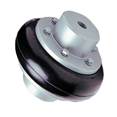
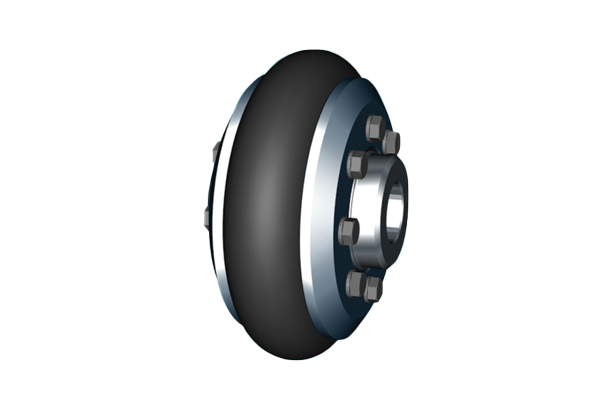
- Tyre Couplings: These couplings have a high degree of torsional flexibility and are suitable for applications with substantial misalignment and shock absorption requirements, like in heavy-duty machinery and construction equipment.
- Pin and Bush Couplings: These couplings use rubber bushes to provide vibration isolation and accommodate misalignment. They are used in various industrial applications, including conveyors, mixers, and crushers.
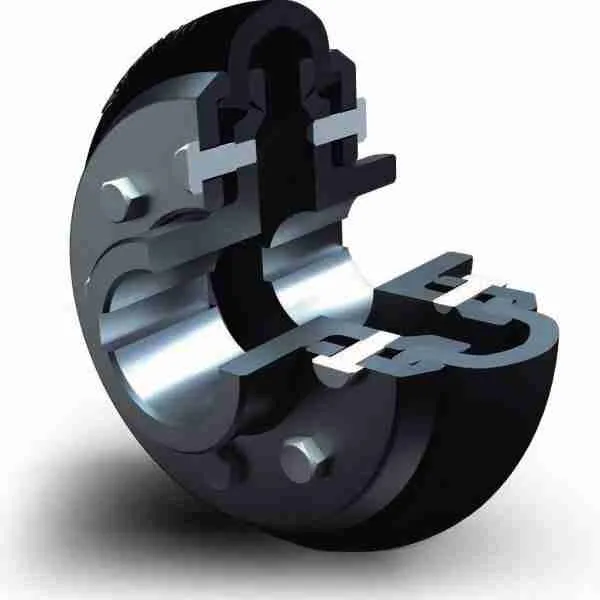
- Diaphragm Couplings: Diaphragm couplings use a flexible rubber diaphragm to transmit torque and compensate for misalignment. They are commonly found in precision equipment like servo motors and robotics.
Each type of rubber coupling is designed to address specific needs in different applications. The choice of coupling depends on factors such as the degree of misalignment, torque requirements, shock absorption, and the level of precision needed.


editor by CX 2024-05-02